| 1 - Removing the front |
|
Remove the 2 torx screws holding the clip bracket at the front on the left hand side of the unit.
Note that The picture below shows a ML/CLK COMAND with the clip brackets, the E class one has other right angle brackets.
|
|
|
|
Here is the right hand side with the screws removed. The mounting brackets then unclip from the unit.
|
|
|
Having removed the brackets and 4 screws you will see one more screw under each bracket and one that was above each of the brackets - it is these that hold the front section in place.
|
 |
|
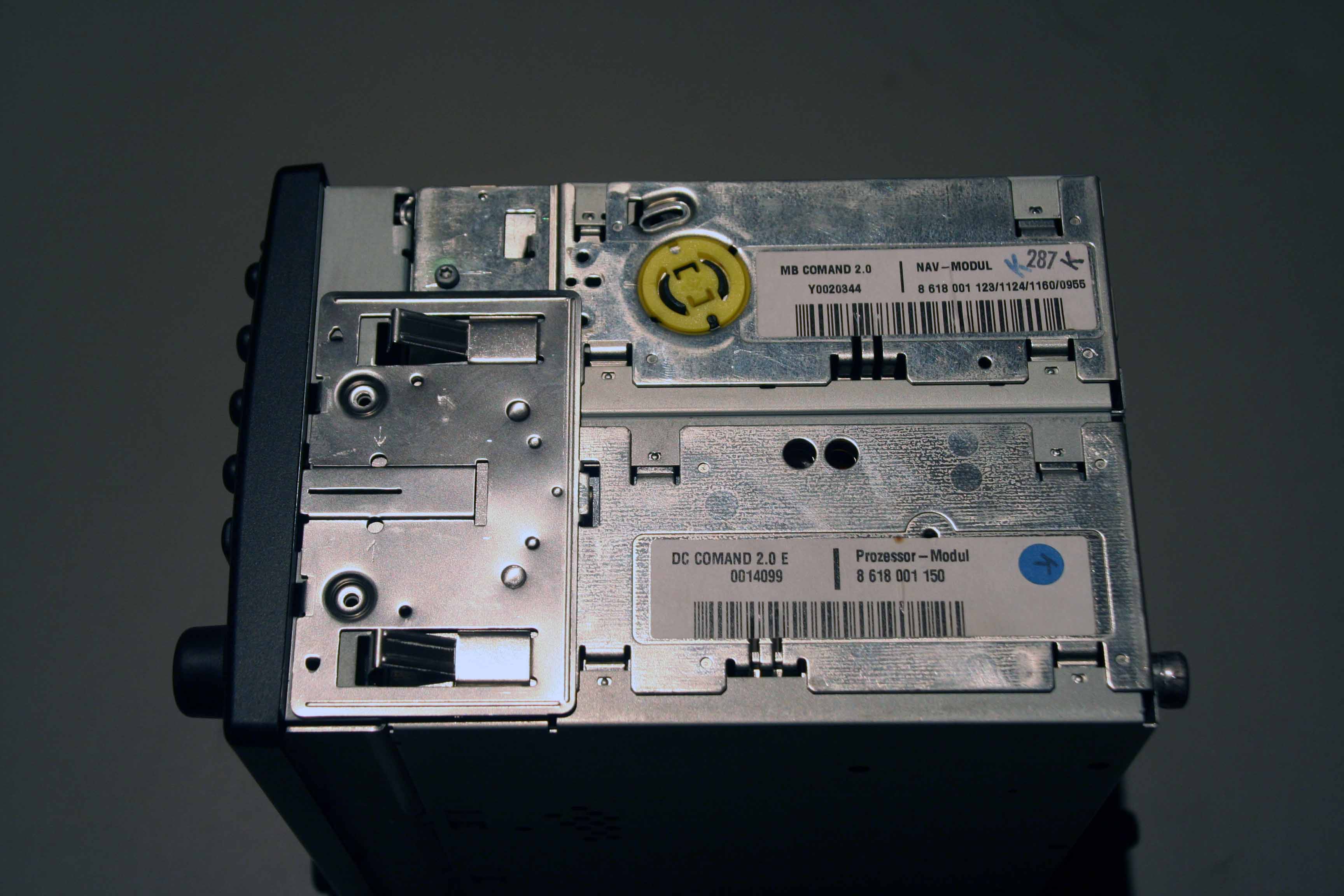
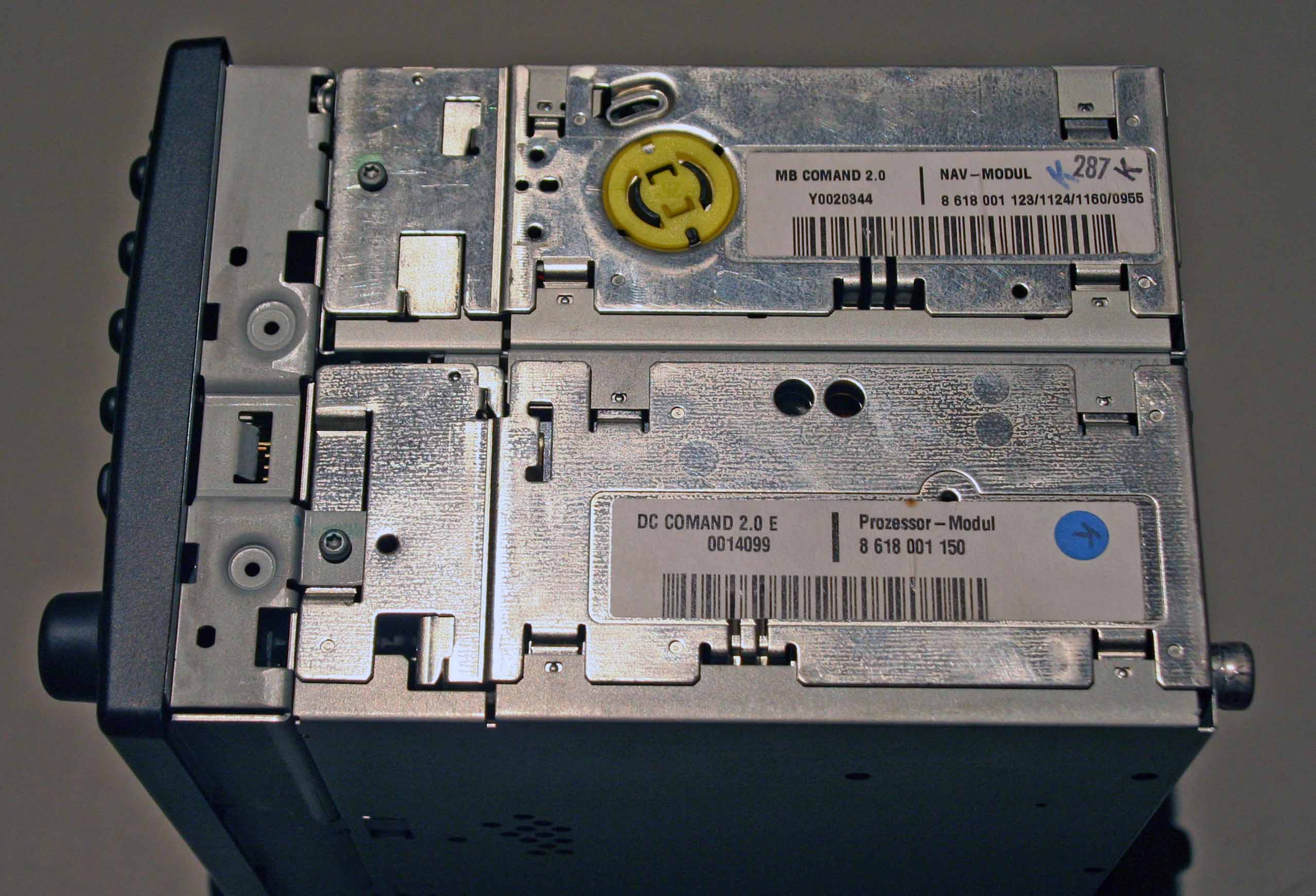
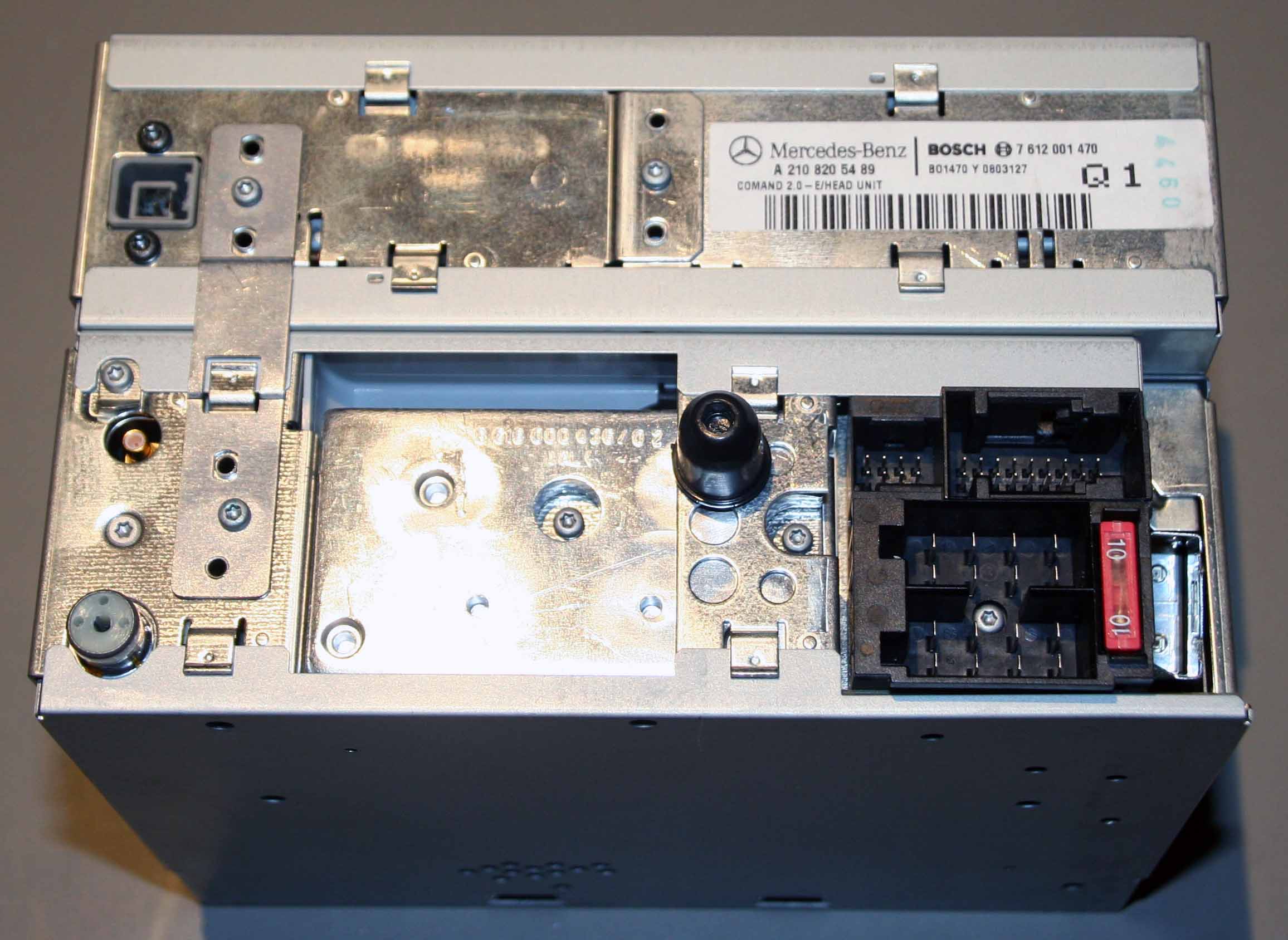
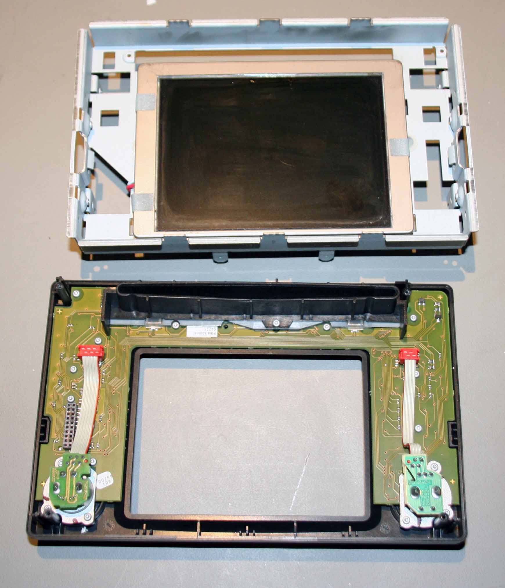
Having removed those 4 screws (two on each side) you can then seperate the front from the rear by pulling the front straight out. It is important that it is pulled squarely and straight to protect the connector. Here is a picture of the rear of the front section when it is removed.
|
 |
| |
| 2. Seperating the top and bottom sections |
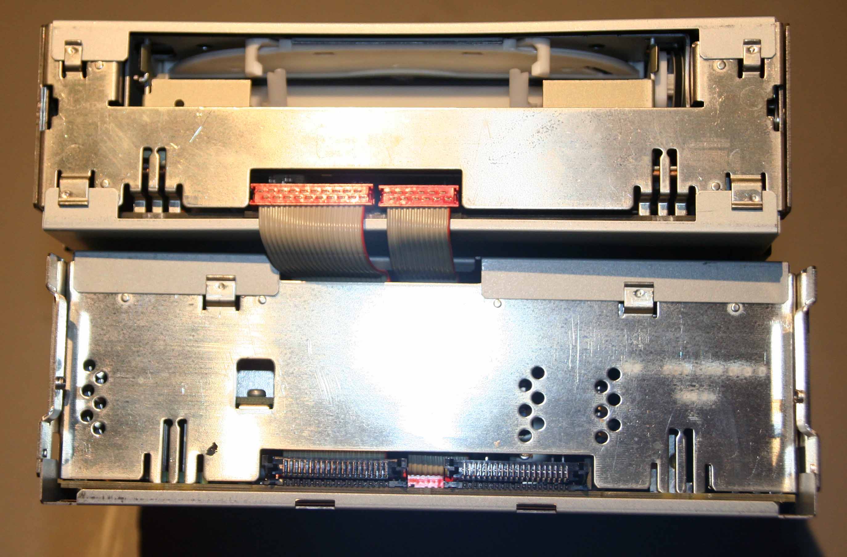
| Carefully pull out the red connectors which connect the wiring between the sections, pull them straight toward you - its a bit fiddly. |
 |
|
And remove the bracket on the left at the back by removing the two torx screws
|
 |
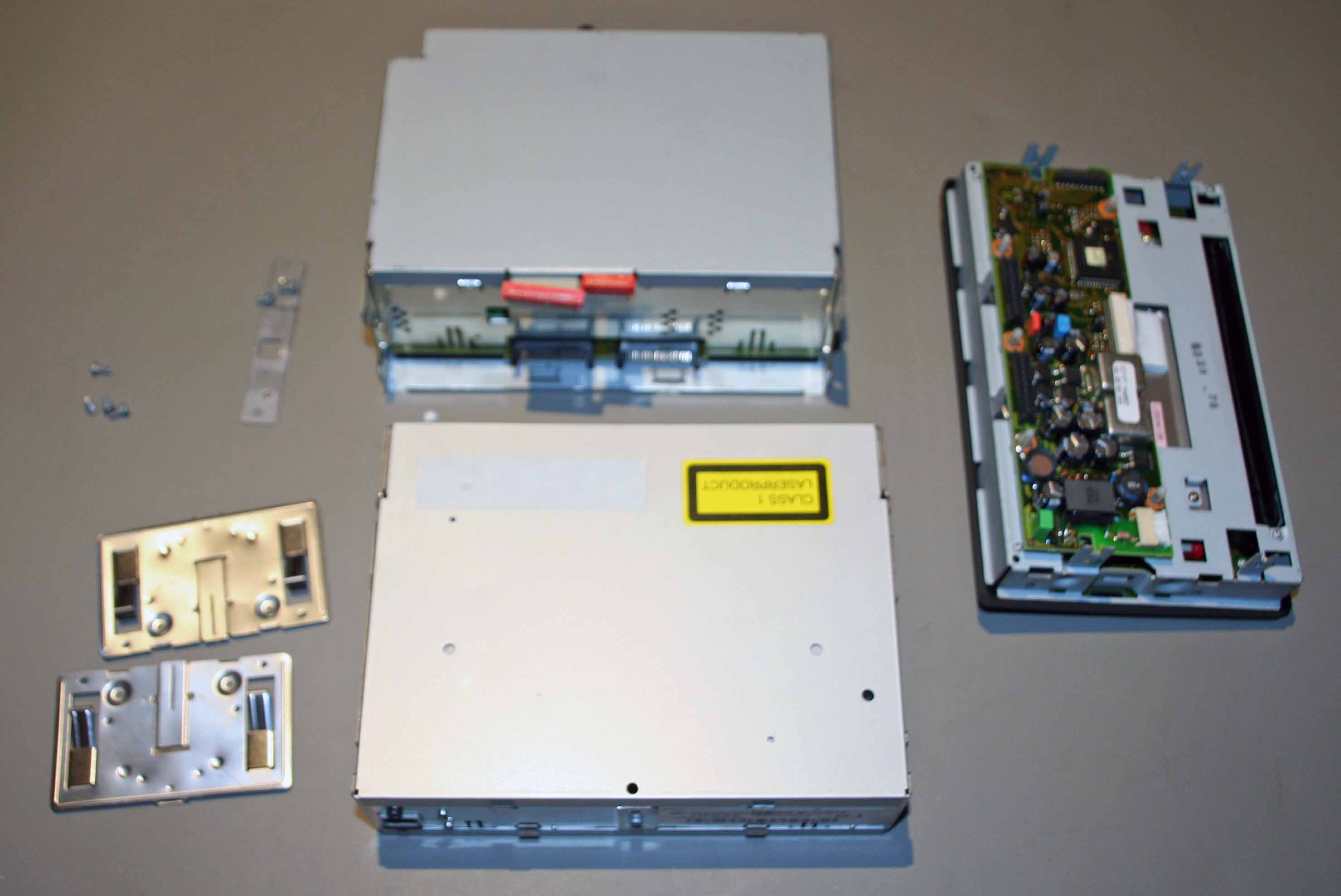
| You now have the COMAND unit seperated into it's 3 different modules. You can remove the covers of the modules by gently levering it up all the way round. |
 |
| |
| 3. Inside the bottom section |
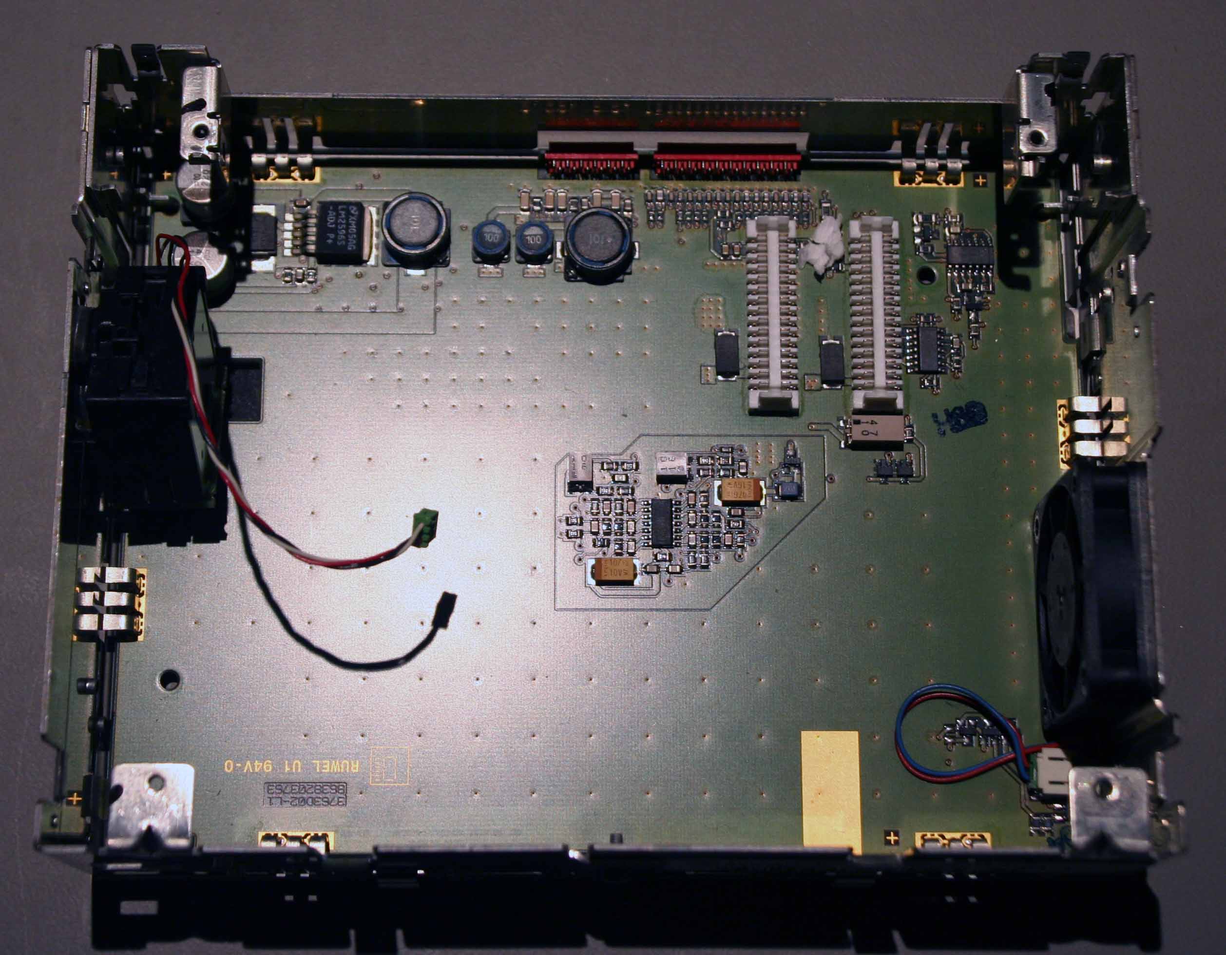
| Here is the bottom section with it's lid removed |
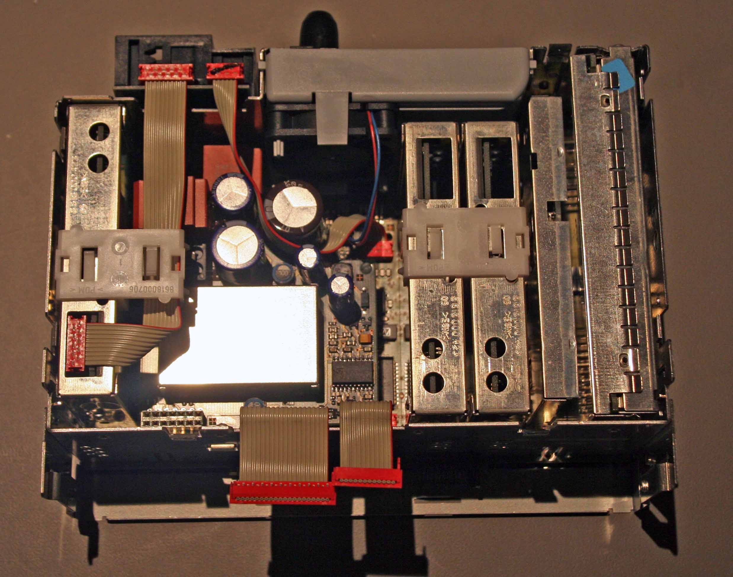 |
| That is about as far as you can dismantle the bottom section without a soldering iron. |
| |
| 4. Dismantling the front section |
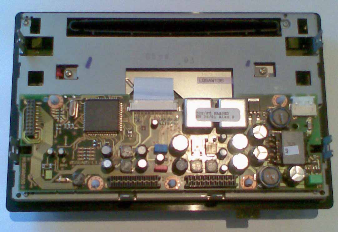
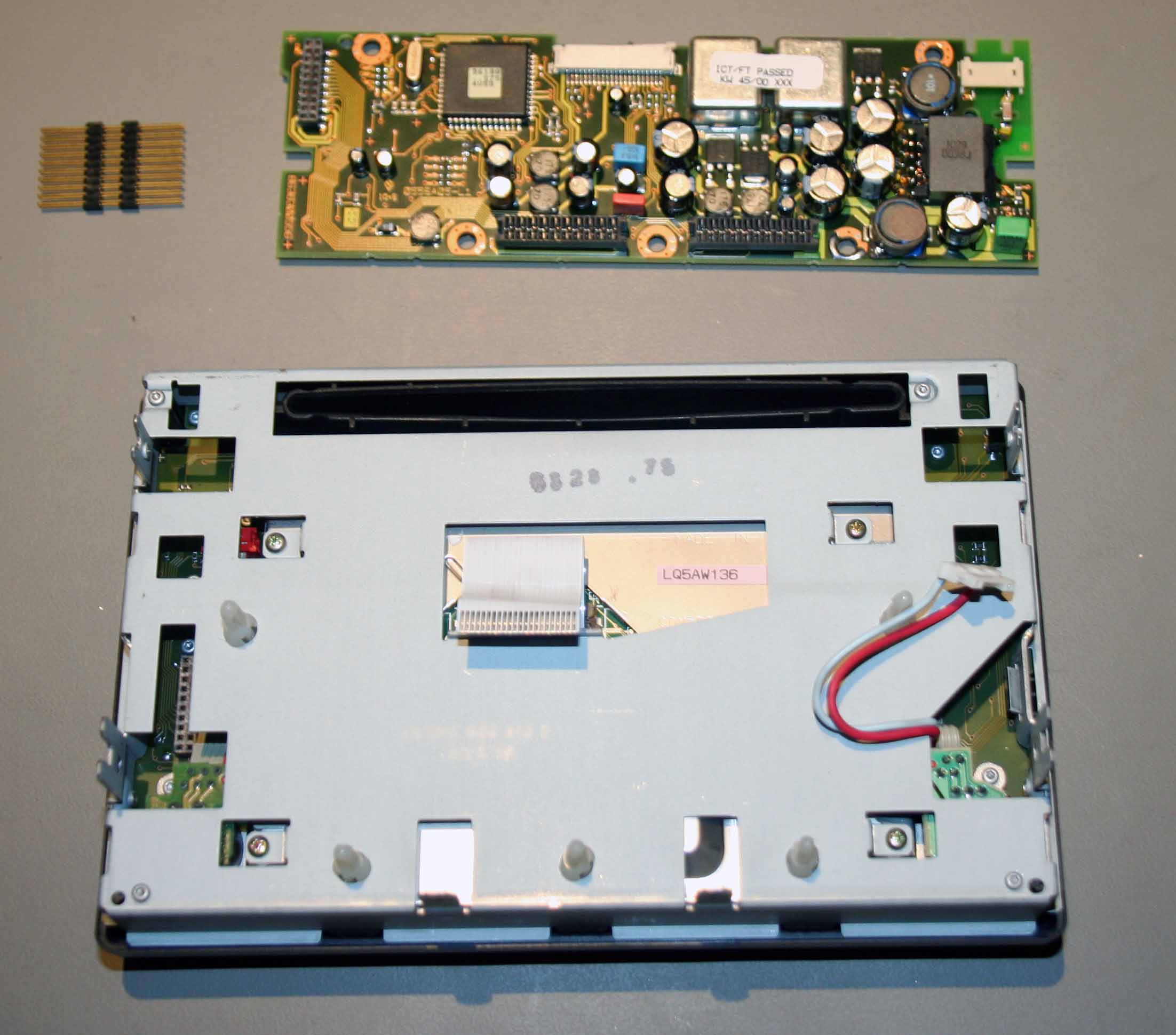
| Referring to the picture of the front section above, pull out the white connector at the right of the circuit board (this is the backlight power connection).
Then using a pliers squeeze the protruding part of each of the 5 white clip-posts (roughly at each corner of the circuit board and one in the middle on the lower edge) and pull the board up just far enough to stop the clip in the post returning to its original position. Once all clips are released pull the board upward squarely (otherwise connectors will bend) - this is what the unit then looks like. I have also remove the connector, which is on the left of the picture.
|
 |
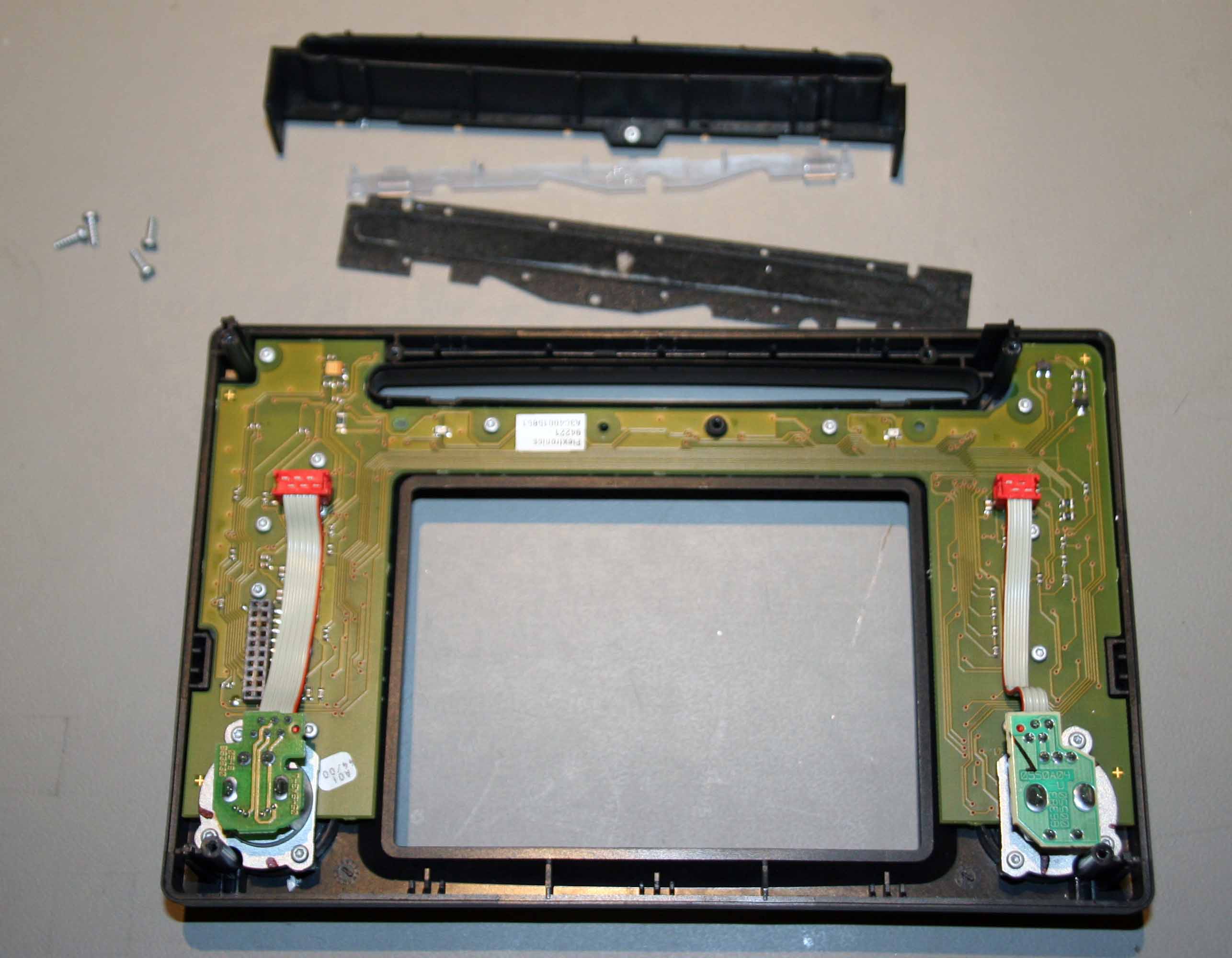
| You can now remove the 4 small screws (one in each corner) and seperate the keyboard section from the display section |
 |
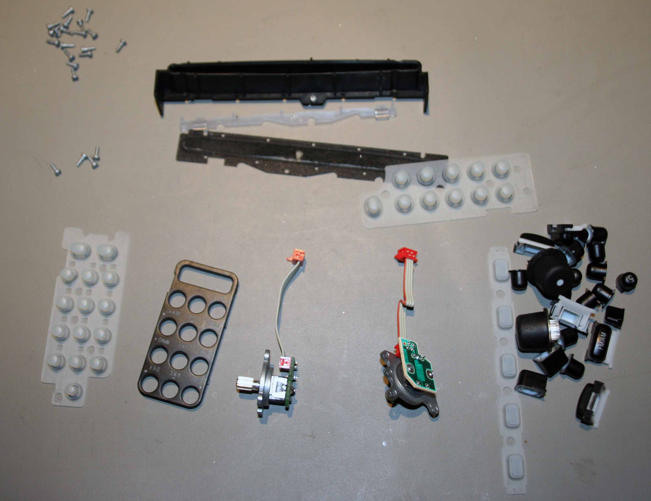
| Dismantling the rest is just a case of undoing the screws. |
 |
 |
| |
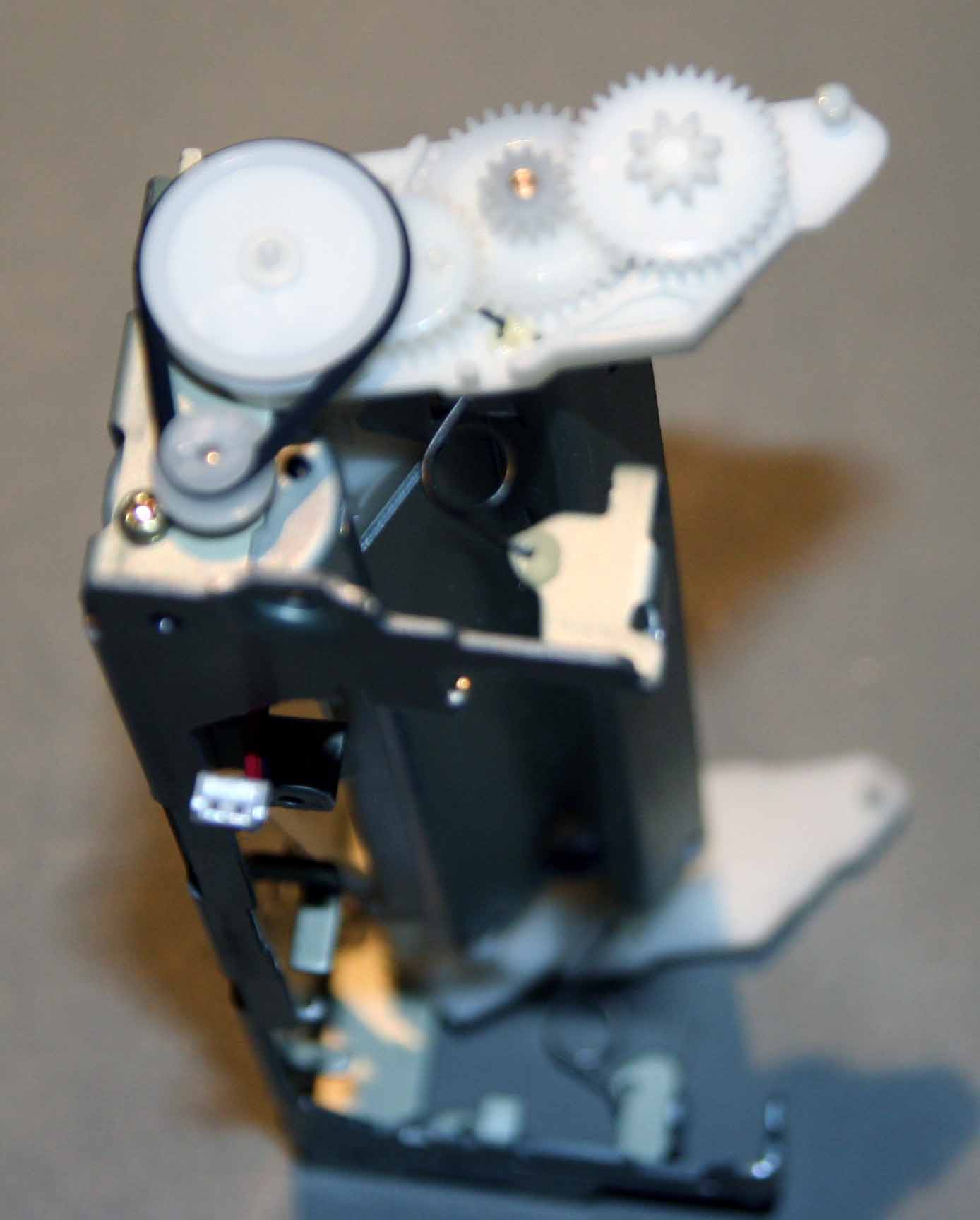
| 5. Dismantling the top section |
| Heres a picture of the top section, note that I have already removed the four torx screws that hold the CD changer mechanism in place. |
 |
|
Before removing the CD changer you will also have to unscrew the GPS aerial connection, that is done by removing the black torx screw you can see at the bottom left of the picture (on the rear panel of the COMAND, above the grey square GPS antenna connector).
As you remove the CD changer you will need to unclip the 3 way green connector that goes to the black gyroscope that is attached to the left side (in above picture) of the top unit.
Having remove the CD changer, the top section looks like this - you can see the gyroscope with its 3 wire green connector in the picture.
|
 |
| |
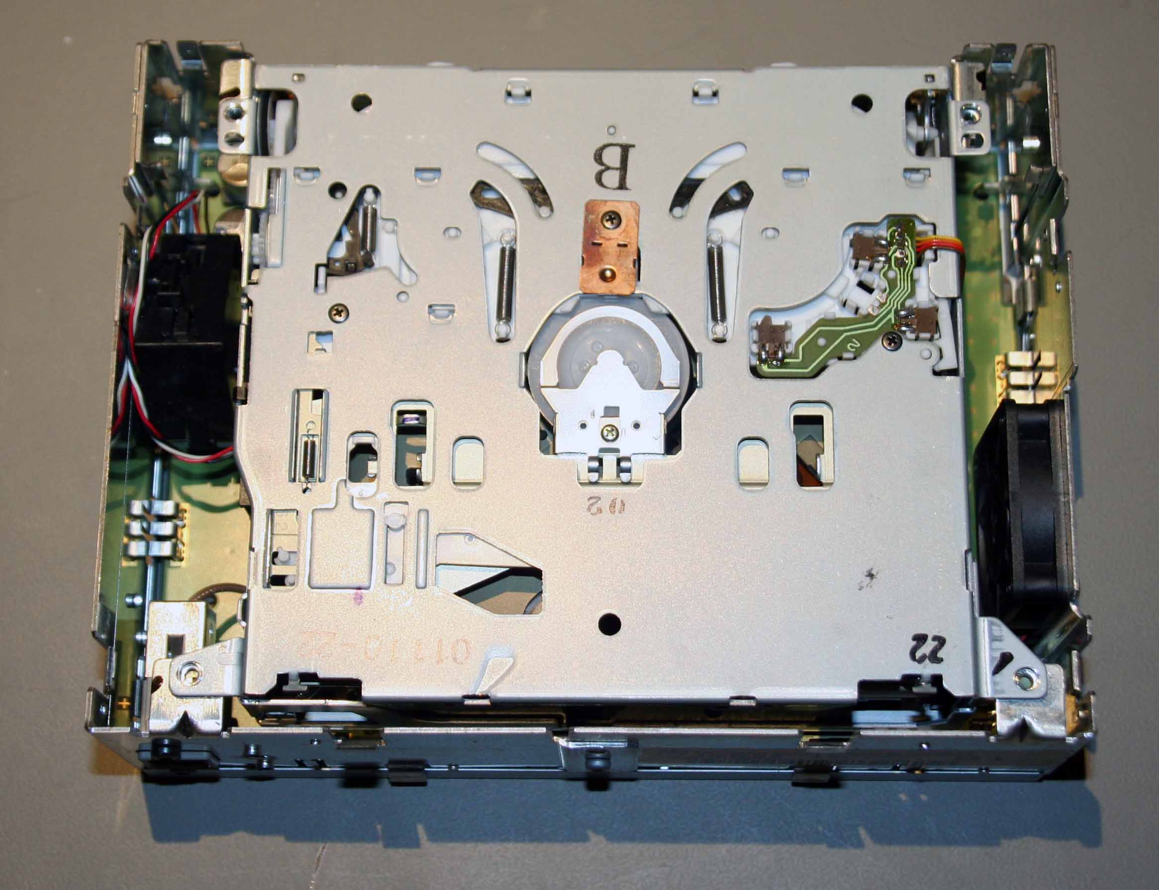
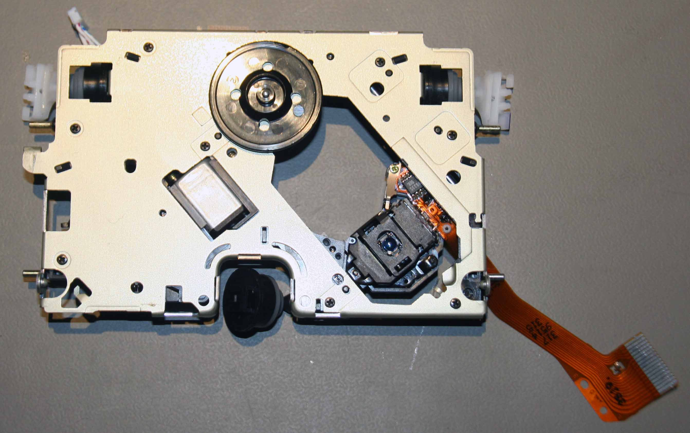
| 6. Dismanting the CD drive |
| This is the underside of the CD drive, which shows the navigation processor board (the larger circuit board), the GPS board (bottom left) and the cable to the GPS antenna socket. |
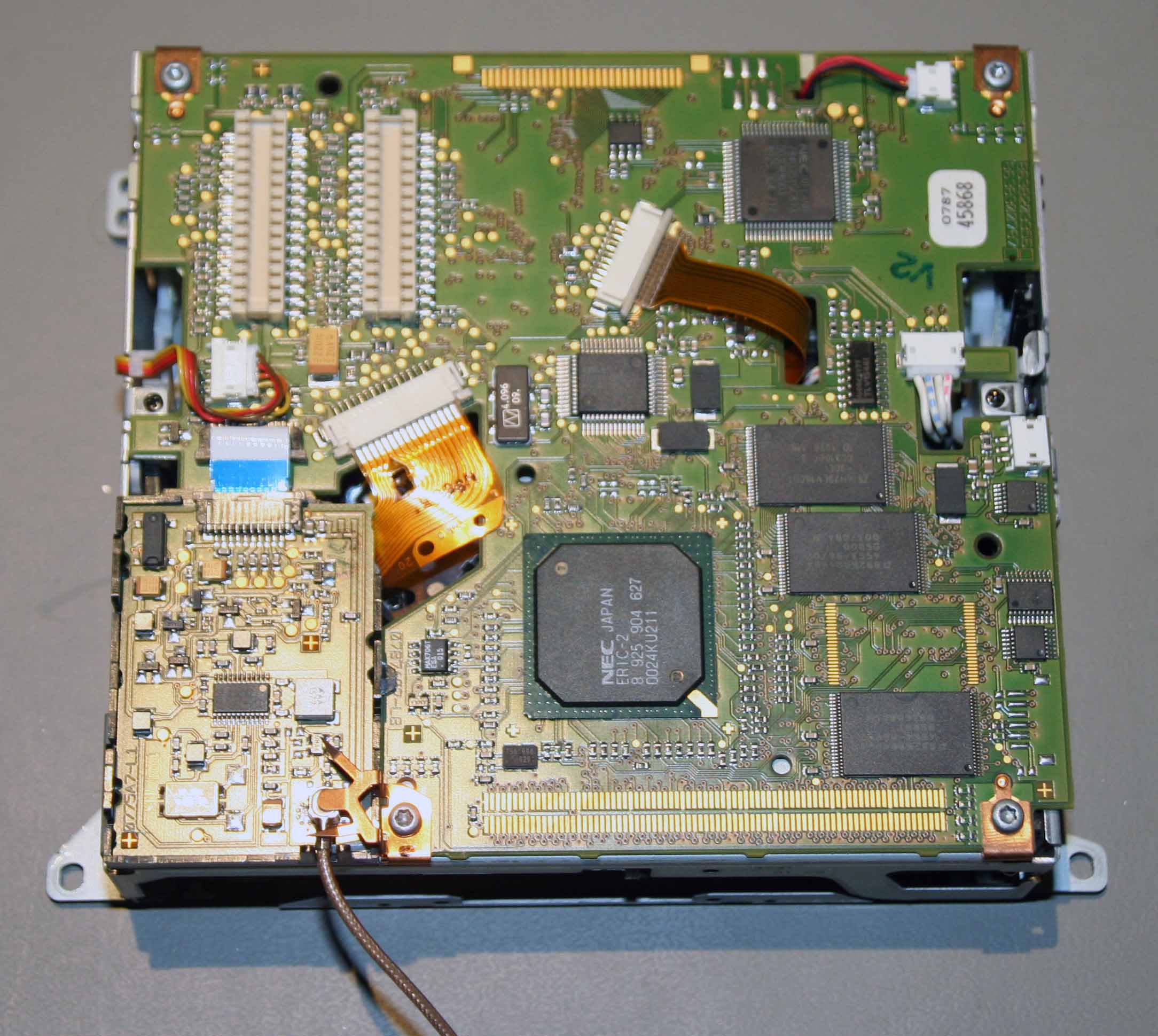 |
| To remove the circuit board, disconnect all the connectors - the ones with ribbon cables have a sliding lock that you slide in the direction of the cable, and then the cable will pull out really easily.
Then remove the 4 torx screws and remove the navigation PCB
The GPS receiver circuit is held in place by the plastic frame around it, and can be removed by gently bending that plastic frame by the clips that hold the litlle circuit board.
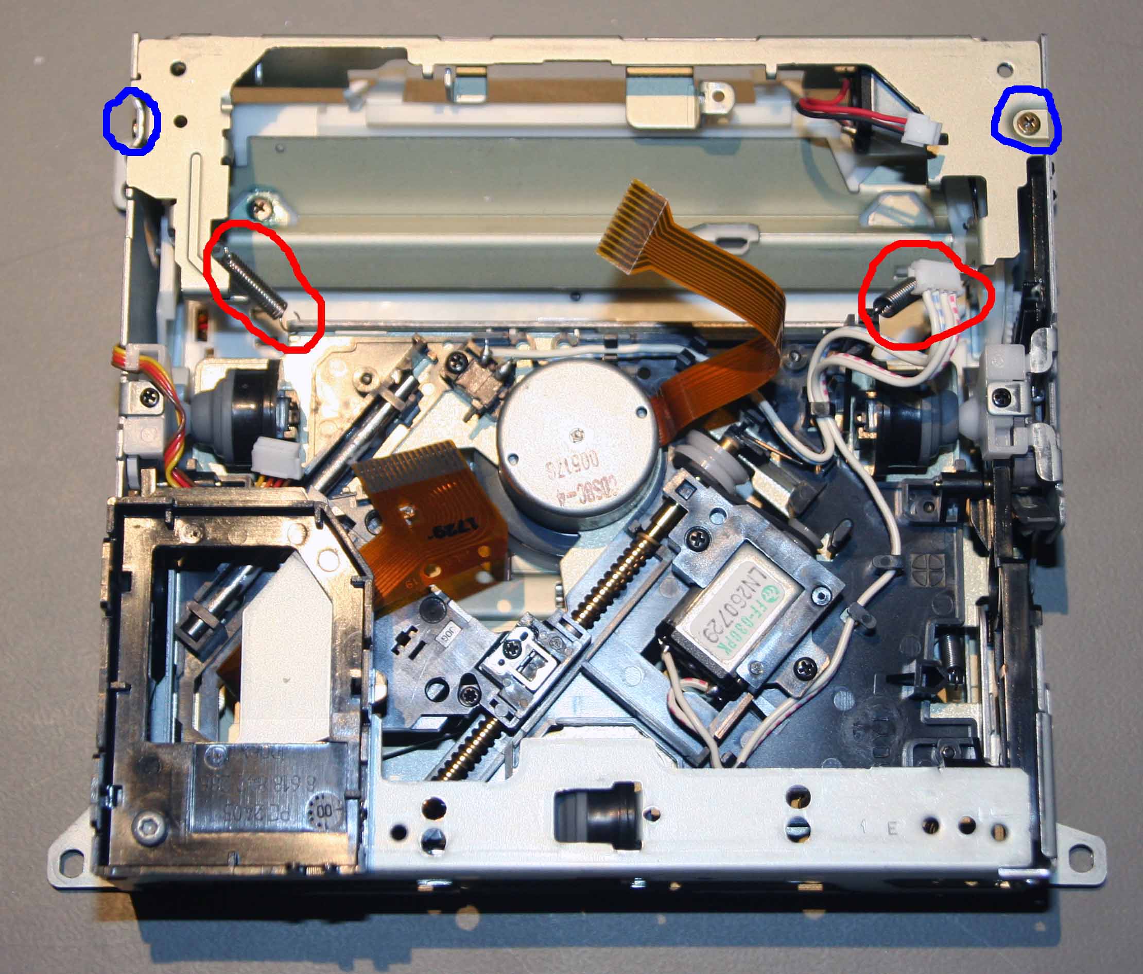
Having removed the navigation PCB you can now get at most of the CD changer mechanism.
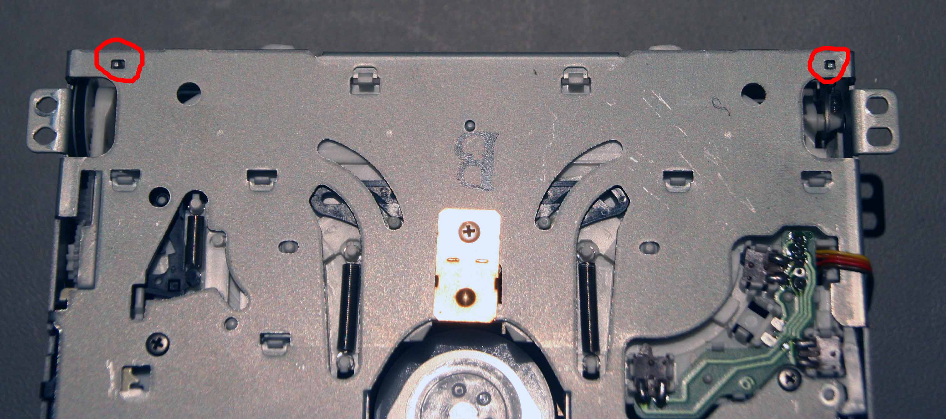
You now need to carefully unook the two springs circlied in red in the picture below, noting their exact orientation (otherwise they will drop off once you put a CD in !), and remove the two gold head small screws that are circled in blue in the picture.
|
 |
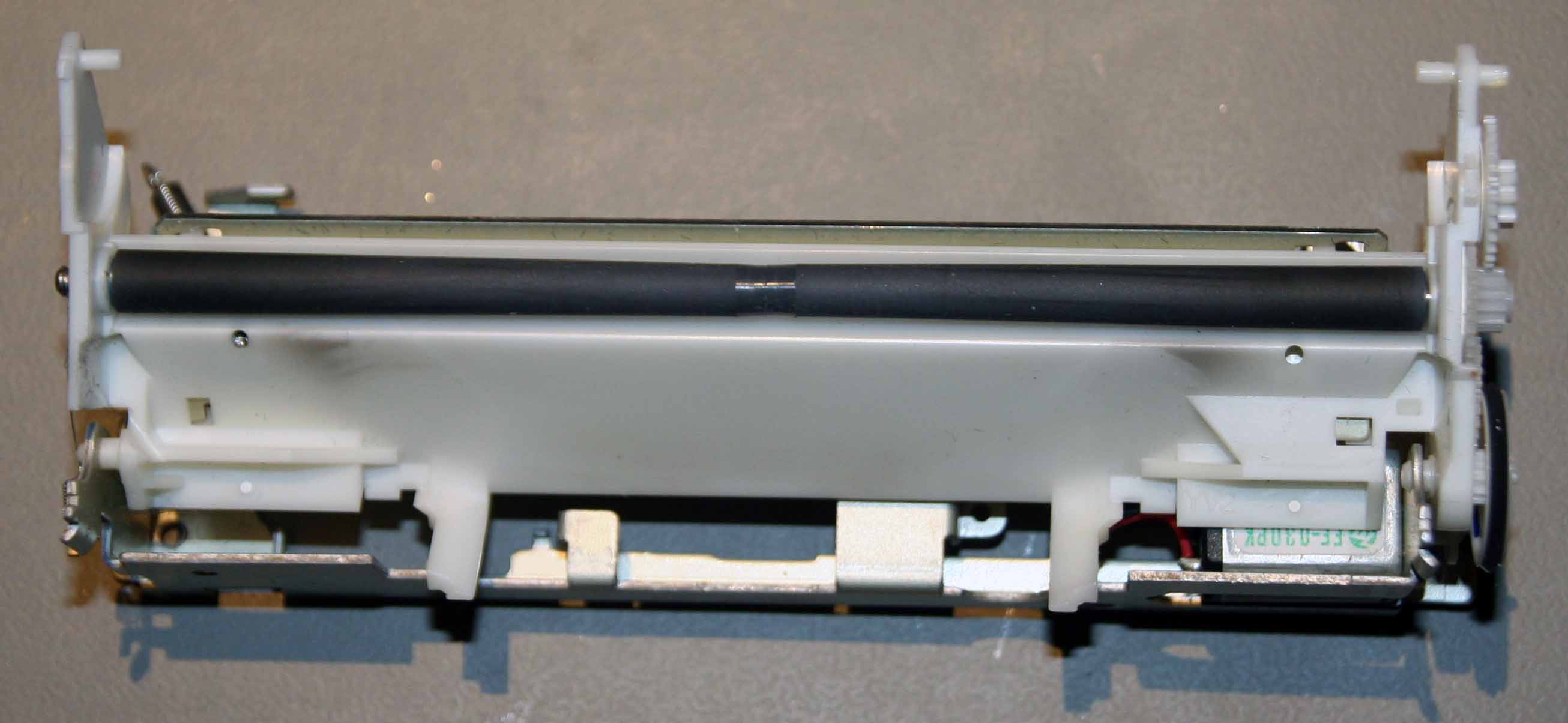
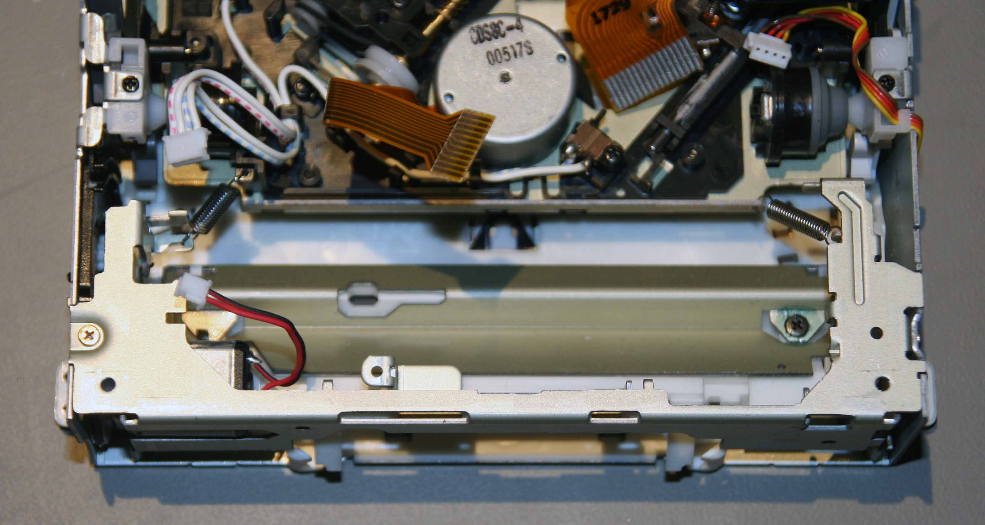
| You can then carefully pull out the roller mechanism. You should clean the roller and the white plastic section with surgical spirit and a clean lint-free cloth. |
 |
|
Having removed the roller, you can get at the CD laser lens with a cotton bud dipped in surgical spirit. You can not easily see the lens, but it is on the other side of the black mechanism with the larger ribbon cable.
Here is a picture of a removed laser mechanism so you can see the lens - do not try and remove the laser mechanism to clean it though.
|
 |
| |
| 7. Reassembly |
| And, finally, in the words of the wise, re-assembly is the reverse of the disassembly.
The most difficult bit is getting the roller mechanism back in place, it must sit in the two rectangular locating holes along the top edge of this picture
|
 |
| When you re-insert the roller mechanism, it should be in the following position |
 |
| And, really finally, here is a picture showing the orientation of the springs which is very very important |
 |
| |
| Please don't blame me if you break your COMAND unit, it is completely up to you whether you want to risk taking yours apart. |