
 |
!! Please select country!!
Created: 30 Nov -0001
Last Updated: 19 Oct 2005
|
Retrofitting and
upgrading Telephone systems in European MY2002-2004 Mercedes ML (W163). Version 1.2 October 19,2005 Correct
LHD/RHD text for phone consoles Version 1.1 October 18, 2005 More
part numbers, some clarifications after feedback. Add
various pictures gathered from the net Add
unanswered questions section Add
cradles section Cheaper
ways of buying parts Version 1.0 October 10, 2005 Initial
version Introduction This document describes
retrofitting and upgrading portable (mobile/cell) telephones in Mercedes ML
vehicles, from the Model Year 2002 facelift (with turn signal indicators in the
door mirrors), to the end of the production of the W163 ML. This document refers to European vehicles,
but I�m reasonably sure can be used to fit European phone systems into US
vehicles. There are some hints and
fitting phones into older ML�s, but these are collected from other people�s
experiences, as I�ve only ever fitted a roof aerial to a Pre MY2002 ML. There are also some hints
for US vehicle owners wishing to install Nokia 6310i phones or the UHI system. I strongly recommend, that
if you want to install the UHI system (the one with different cradles for
different phones) in a MY2002/2003 car without an existing phone, or with just
a phone (no CD changer or digital BOSE system) , or in an older ML that you
contact Steve at MBenzNL (see www.mbenznl.com)
and use his retrofit kit. You may need to ask him for a D2B harness, and If you
have BOSE or CD in your vehicle you will need a D2B joiner. His retrofit kit
does not put control units under the seat, it puts it where MB dealers would
retrofit phones. You may find it easier to use my aerial harness converter than
to run a new aerial lead. If so, you will also need to join the male and female
aerial connectors under the front-right-hand seat. WARNINGS The vehicle must be on a
flat surface when working on it with the parking brake on and the wheels
chocked to prevent the vehicle from rolling if it is in neutral. The seat and
seat belt bolts must be re-tightened to the correct torque – they are
critical safety parts. Disclaimer, I don�t warranty
the information in this document, part numbers may be wrong. If they are,
please let me know, and I will update the document at some point in the future.
If you destroy your vehicle, that is your problem, and you understand that by
following these instructions I accept no liability for what happens to you,
your friends family, or anyone else or to your vehicle. How do I tell what Model
Year my ML is ? MY2002 vehicles were the
first ML�s with indicators in the mirrors. Near the door hinges on one of the front doors is a black
sticker with the vehicle identification number and all the build options
printed on it. If you look at the
lower half of the label, there are many 3-digit codes. Look for the codes
starting 80x. 800 is MY2000, 801 is MY2001, 802 is MY 2002, 803 is MY 2003 and 804 is MY2004. (model year codes are 800 to 809)
– so 808 is MY1998 and 809 is MY1999 on W163 ML vehicles. Other interesting codes are:
- 352
– Comand. 852
and 854 are the Nokia 6210/6310 installations 386
and 388 are the UHI phone installations. 810
- Bose sound system 819
- CD changer What was fitted as
standard if a mobile phone was ordered from the factory? MY2002 vehicles were fitted
with fixed Nokia 6210 or 6310i phone systems. I�m not sure when vehicles
changed between the 6210i and the 6310i systems. At MY2003, the handset holder
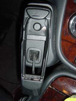
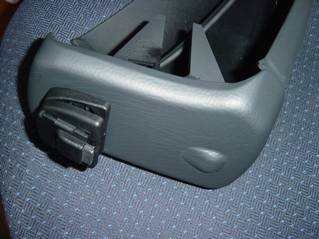
was also changed to the newer 6310i type holder (curvey, not square). Picture of MY2002 ML handset
cradle.
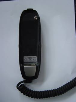
Picture of curvy cradle
similar to that fitted in MY2003
MY2004 saw the introduction
of the UHI interface, which has a changeable cradle, where different cradles
are used to support various different phones. A number of
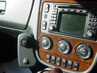
Nokia/Siemens/Motorola/Sony handsets are supported. Picture of MY2004 phone
console (UHI) without the handset cradle.
What parts make up a
phone system? 1) The phone itself 2) The cradle and it�s clips and screws 3) The phone console 4) Wiring between the cradle and the control unit
mounting plate 5) Fibre optic loom to the control unit from the head
unit 6) The phone control unit (and mounting screws) 7) The E-Net compensator (and mounting screws) 8) The mounting plate for (6) and (7) 9) The wiring loom for (6) and (7) 10) Aerial and Aerial wiring Was any of this pre-wired
by the factory ? The European ML�s were
pre-wired with the phone wiring ((4) in the above list) and the aerial wiring
(10). The MY2004 (UHI) wiring is different to the MY2002/2003 wiring, and the
UHI wiring is not available to order from Mercedes on it�s own. The fibre optic loom was not
pre-fitted, and is different depending on which Audio options you specify. There are 2 cables that go
from the roof (by aerial hole) with FAKRA connectors on them, one goes to
behind the dash and ends up as a WICLIC connector – this is for the GPS
connection to COMAND. The other goes to a WICLIC (MY2002/2003) or Black FAKRA
female (MY2004) under the seat. Then there is a cable from there (with the
opposite sex WICLIC or FAKRA) that goes to behind the dash for the phone. At
the dash end it is either a Mini-UHF (MY2002/2003) or a purple FAKRA female.
These are for the phone. The connectors under the seat will connect together if
you want an aerial connection from roof to behind the dash. There are apparently some
MY2003 RHD ML�s that seem to have the correct connectors behind the dash and
under the seat, but only the phone antenna seems to appear in the roof,
connected to an older style aerial connection at the grommet in the middle of
the roof. In fact, the blue GPS FAKRA is somewhere to the left of that, and if
you follow the coax from the aerial connection, you will find the purple FAKRA
connector for the phone aerial. What parts do I need if I
want to install a phone system? For all sections below, I
have assumed that you have a roof antenna – because I have assumed you
wouldn�t be installing this unless you have COMAND. The roof aerial part number
is A163 820 15 75. The phone console parts and
microphone/cover are colour coded to match the vehicle interior. These codes
are shown as WWW, XXXX or YYYY in the tables below. Black (Anthracite) VVVV=7D05 XXXX=
7211 YYYY=9B96 Orion Grey VVVV=7D05 XXXX=
7214 YYYY=7E33 Java VVVV=8G13 XXXX=
1434 YYYY=1A68 General Notes for all
vehicles Mercedes sell various
retrofit kits of parts, which are often significantly cheaper than purchasing
the parts separately. These include the microphone
and it�s surround, which is about 1/3 of the cost of buying the 2 parts
separately, and the MY2002/2003 E-Net Compensator (about half the cost
purchasing a kit with it in rather than the E-Net compensator on its own) The part numbers in the
lists below show the pricing for the kits that I have found (which normally
start (B6 xxx xx xx). US Vehicles may have the
microphone already installed. If you have the Garage Door opener, but no
microphone, then you should purchased the Microphone+surround as shown in the
parts sections later in this document, plus a surround with cut-outs for
microphone and garage door opener, and move those parts to the new cover, The
cover with the garage door opener and microphone cut-outs is part number A163
820 15 12 VVVV. (See above for
what VVVV is). The factory standard fit
phone consoles shown below are slightly awkward to fit, and you may prefer to
use the parts in this table if you don�t mind that it doesn�t look identical to
the factory fitted version: -
MY2002 changing from a
6210 system to a 6310i system
All you need for this
upgrade is to replace the control unit under the front right hand seat. Wind
the seat fully forward, and you can see the old unit, and using a TORX T20
socket wrench, you can unscrew it. The big connector removes by squeezing the
sides, the fibre optic plug removes by pulling straight out – be careful
not to bend the fibre cable harnesses. The part number required is
A203 820 25 85, or it�s replacement A203 820 51 85. Technically, the 6310i
handset can fall out of the original MY2002 6210 cradle, and a MB service
bulletin suggests changing the cradle to a newer part, however, this never
happened to me! If you are going to change it, change it to the MY2003 parts
shown below. MY2002/2003 installing a
6310i system (with MY2003 phone cradle) The following parts are
required: -
The E-Net compensator boosts
GSM1800 signals, (newer GSM networks use GSM1800, such as Orange and T-Mobile
in the UK) – the part number shown above is the cheapest way of ordering
it (it comes with a C class saloon Nokia 6310i (non UHI) wiring loom which you
can ignore, or send to me please!) – if you wanted to order it the
expensive way, it�s part number A203 820 39 26 (although its always worth
checking one price against the other). However, the system tends to
work fine without the E-NET compensator and in fact MB have stopped fitting it
in MY2005, so you may like to ignore it and the DC-Separation filter – it
is an expensive part. MY2004 installing UHI
system The following parts are required:
-
MY2003/2003 installing
(or changing to) a UHI system All the parts for the MY2004
UHI system are needed - however if you are upgrading from an existing
6210/6310i setup to a UHI system, then you will not need the phone console
mounting bracket and screws or screw eye, the under seat bracket, the
microphone or it�s surround and the E-Net compensator as they are already in
your vehicle. You will have to make up a
special wiring loom and modify the under-seat wiring loom so you also requires
the following: -
What Tools are Needed
?
Fitting the phone
systems MY2002 changing from a
6210 system to a 6310i system All you need for this
upgrade is to replace the control unit under the front right hand seat. 1) I suggest you remove the
phone fuses first. The phone controllers can be a bit sensitive to power
surges. They are F21 and F10 in the engine compartment fuse box. 2) Wind the seat fully
forward, and you can see the old unit, and using a Torx T20 bit and socket
wrench, you can unscrew it. The big connector removes by squeezing the sides,
the fibre optic plug removes by pulling straight out – be careful not to
bend the fibre cable harnesses. 3) Reconnect the new part,
and screw it back in. 4) Reinstall fuse and test. 5) You should have the
COMAND system recoded by the Mercedes dealer at some point to tell it has an
extended phone system – then you will be able to use SMS functionality
from COMAND. MY2002/2003/2004 Install
where no existing factory fitted phone This section covers
installing the MY2003 phone (Nokia 6310i) in a MY2002 /2003 vehicle, or the
MY2004 (UHI) system in a MY2004 vehicle which does not have the factory fitted
phone installed. If for some reason you have the non-portable phone installed,
then the D2B wiring is already in place and you have the under-seat bracket,
and thus some steps do not need to be done. Note also, that I have
assumed you already have the GPS aerial on the roof, because you have COMAND. 1) Remove the COMAND unit
using the release keys – be very careful removing the D2B connector
– you must avoid bending the orange fibres too much, or they will break
internally. Remove the release keys from the command by pushing them back in,
and pressing where the arrows shows on the side of the COMAND unit, and remove
the keys. 2) Find the phone harness,
which is taped somewhere below the COMAND, and the aerial connector. On
MY2002/2003 the aerial connector is a silver mini-uhf. On MY2004 it is a dark
red/purple �FAKRA� SMB connector. The handset connector is a black multi-way
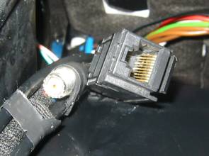
connector. Picture of MY2002/2003 Phone
connection behind dash
3) Wind right hand seat
fully forward, and you will be able to see a set of wires in a black Hessian
type cover, cable tied to the rear of
the seat frame. Cut the cable ties and then remove the seat and the
air-vent below the seat (by unscrewing the T20 torx screw). Removing seat: - Lower
or Remove headrest Remove
the TORX bolts from the rear of the seat, wind seat fully rear and remove rear
ones. Detach
electrical connector for seat electrics. Remove
seat. Note
seatbelt is still attached, so it has to stay near vehicle 4) Assemble all control
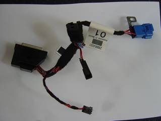
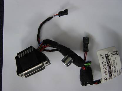
units and wiring loom onto mounting plate. Here is picture of the
under-seat wiring loom – this is the UHI version. The non UHI version has
one less black connector (the one in the middle of the picture is not there)
and the connector at the top middle is different. The connector at the left of
the picture connects to the phone controller. The bottom connector is for the
E-Net compensator. The blue connector connects to the main car loom, providing
microphone, power and connection for voice-recognition switch. The other 2
black connectors connect to the phone cradle.
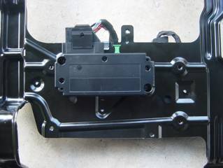
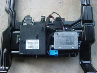
Picture of underside of
MY2002/2003 (nokia 6310i) loom, controller and mounting plate, with E-NET
compensator. The plate is fitted
in the car with the end at the top of the picture at the front of the car. The
holes in the plates go over the holes where the seat bolts fit.
if you are using the
MY2002/2003 E-Net compensator, then the DC separation filter is installed
connected to the picture of phone on the E-Net compensator. The MY2004
compensator does not need an external filter. 5) Install the D2B fibre
loom connecting between the seat and the COMAND unit. Remove
the right hand door sill cover (lever up the chrome part of the door sill,
there are screws under it to remove the plastic bit) Remove
right hand kick panel and under-dash panel Run
the D2B fibre optic loom from the head unit (along dash panel, under carpet
along door frame, under carpet and pop out under removed seat) . If you look at
the loom, one end has a right angle radiused bend about 2-3 feet from the end
– that is the COMAND end. Re-install
sill and kick panel etc. 6) Plug all connectors on
mounting plate, including the fibre optic one, and place the mounting plate in
position (it fits over the seat bolt holes). If you are not using the E-Net
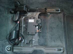
compensator, plug the two aerial connectors under the seat together. Picture of under-seat
mounting plate in position.
7) Install the phone
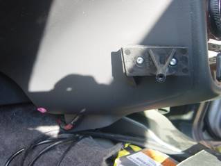
console, and plug in wires. The pictures below are of a
right hand drive ML with the bracket installed. The purple clip at bottom left
of the dash-board is for the lower screw of the console.
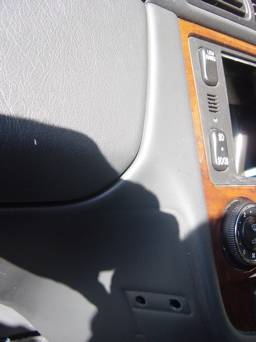
In order to fit that bracket
two holes must be drilled in the centre console to mount it– These are
8.5mm holes, 32 mm apart. The front one is 35mm away from the front of the
console, 245mm below the top of the section of console it is mounted on (i.e to
the join below the vents just visible at the top of this picture). The rear hole is slightly lower, so that the
front of the bracket is roughly parallel to the front of the centre console, so
that the front of the phone console ends up parallel to the wood dash board.
Here is a picture of the
Right Hand Drive phone console not quite assembled.
It is not completely
assembled, because the bracket is fixed to the centre console first, then the
rear section fixed to the bracket, then the front section is clipped on,
followed by the UHI surround, which is screwed in (holding the front section to
the rear section), then the UHI connector is clipped in place, so you should
only clip all the parts together as you assemble it into the vehicle. The
wiring connections need to be made before the rear section is fixed to the
bracket on the centre console. 8) Connect the D2B wiring
loom If vehicle does not have
Digital BOSE or CD, or Teleaid then there will not have been a fibre loom
plugged into the back of COMAND, so just plug in the one you installed for the phone. If there is one already,
then you have to re-configure it to insert the phone controller into the loop.
You will need to: - (a) open both of the fibre optic plugs at the COMAND end
(the new one and the pre-existing one. Remove both fibres from one connector,
and remove white one from other, and put the white lead from the other loom
into the connector and close it. (b) Join the remaining 2 cables (one from each loom) with
the fibre joiner (red cable will only plug properly into one end, white into
the other). It is really important
that the fibre cables are not sharply bent, and you may have to free up some of
the fibre by carefully removing some of the black corrugated tube from each
fibre cable. 9) Install microphone. Pull
down the cover in the centre of the over-head console Remove
the cover Attach
microphone to new cover Microphone
plugs in to wiring that is above over-head console, you may have to unscrew it
to remove it. Clip
new cover in place, and push closed. 10) Install phone fuse in
fuse box under bonnet. They
are 15-amp in F21, and 10-amp in F10 – if they are not there already. 11) Re-install COMAND and
test that the phone works. 12) Re-install Seat. (The
seat bolts must be done up to 40Nm torque this is vital for safety purposes) 13) You should, at some
point, get your Mercedes dealer to configure your COMAND system to know that it
has �telephone with extended features� – they should know how to do that.
If SMS sending doesn�t work from the COMAND unit, it is because they didn�t
tell it that the COMAND that the phone has extended features. Installing UHI System in
MY2002/2003 vehicle This is the most complicated
install because you have to make up new wiring looms to go between the phone
cradle and the control unit, and remove
the centre console to install it. I did consider just making
some adapter looms to convert the MY2002/2003 10 way RJ type plug/socket to UHI
connectors, but the ML UHI wiring loom has shielded twisted pair for the data
signals, and 0.5mm cables for the power supply (because the UHI controller has
0.5mm cables to it from the fuse box), and the existing wiring didn�t obviously
have any of that. Read the MY2002/2003/2004
Install instructions above,
carefully. If you have decided to use
an E-Net compensator, or are upgrading the factory fit Nokia 6210/6310i kit, we
will use the MY2002/2003 E-Net compensator part. It�s possibly cheaper, but
more importantly has matching antenna connections to the vehicle�s pre-wiring.
However, it has a different power plug to the MY2004 version, and so the
under-seat wiring loom needs to have the small 4 way connector (A037 545 65 38)
changed to the 3 way version (A023 545 55 28). This is done by clipping up the
locking clip at the �wiring� end of the connector (it will probably break off
when you open it fully), then using a small pointed object, carefully press the
metal clip on each of the connector elements whilst gently pulling the cable
out – each clip has to be released twice as the cable comes out. Push the elements into the
new connector, using the following table. The new connector is marked with the
pin numbers by where the wires enter. CHECK THE PIN NUMBERS CAREFULLY, you have
to re-arrange the wires.
You also need to change the
2 pin connector on the under seat wiring loom, as the female version of that
connector is not available. Use the Male connector, as it can�t be mistaken for
a microphone connector then, and connect the Red lead to pin 1 and the Brown
lead to pin 2. I tend to crimp and solder the connectors Here is a picture of the
modified under-seat wiring loom.
You then need to make the
main wiring loom, and run it through the centre console and out of the carpet
where the other loom runs [visible when the front right seat is removed].
Again, crimping and soldering the connectors will give the most secure fit. The wiring loom consists of
a piece of FTP (fully shielded CAT5E twisted pair patch cable (not building
cable)) and 2 power lines. For the purposes of this document, I will use RED
and BLACK as the two power lines, although it may be better to use brown cable
as that represents ground on Mercedes wiring. It is easiest to purchase a CAT5E
FTP lead from a PC shop and chop the connectors of it.
The install is then the same
as installing the UHI system in a MY2004 vehicle except that the centre console
must be disassembled and the wiring installed before the phone console is
fitted – if you are upgrading an existing phone system, then the D2B
harness will already be in place, so you will not have to lift the door sill
cover or remove kick panels etc. Installing the cable
between the cradle and the seat. This cable needs to run
along the centre console, and drop down the side of the seat under the carpet. This requires some
dismantling of the centre console. (a) Put gear selector in Neutral (make sure handbrake on,
wheels chocked) (b) Open the centre glove box, and remove the hinge
screws. (c) Insert a flat (plastic) lever into the slots above
the screws to release the catches holding the glove box lid, and pull upward (d) Remove the plastic screws holding in the glovebox (e) Remove the plastic clips at bottom of glove box and
remove it (f) Remove gearshift lever cover (unclips) (g) Remove T20 Torx bolts from rear of wooden panelling
near glovebox (h) Carefully prize up the whole panelling (i) Remove connectors to the panelling (j) Undo the 3 way electrical connector under the glove
box (k) Remove two T20 bolts under glovebox and two by gear
selector, and console will come out (l) When you reinstall, make sure air ducts are fitted
correctly Route new wiring from seat
back to glovebox along side of air ducting. Re-assemble the centre
console before installing the phone console. Here is a picture of the
glovebox lid showing the catches that have to be released through the slots in
step C above.
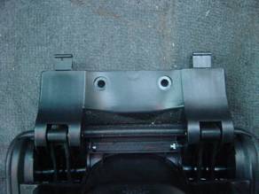
Here are some pictures of
the mounting plate and UHI controllers. Here is a picture of the
assembled mounting plate from the top.
And from underneath - this
picture has the MY2002/2003 E-Net compensator and the voice recognition module
installed – that is the subject of another document!
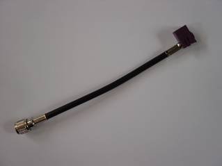
The aerial converter lead
goes between the UHI cradle connector and the existing antenna wiring.
Hints for older ML
owners. In the Pre MY2002 ML, there
is only one aerial cable running from the front to the roof at the back of the
vehicle, so Mercedes fit an aerial splitter and split both GSM and GPS signals
which were fed down the one cable by the one antenna. I suspect that they do not
fit the splitter if you do not have both – but they may do, since it is
also an amplifier for GPS signals. I believe that MY2000 and
before have FME connectors, whereas MY2001 has FAKRA connectors. FAKRA
connectors are SMB connectors with a colour-coded and keyed cover, so that they
will only plug into FAKRA connectors of the same colour. It should be noted that
there may have been a number of instances where aerial cables from different MY
vehicles are fitted, and you should take a look at what you have before you purchase
a splitter or cables. The aerial cable connects
directly to the splitter, and the splitter then has 2 cables, one to COMAND and one to the phone.
Splitter (FME connectors) A163
820 12 89 Cable from FME splitter to
GPS A163 540 01 13 Cable from FME splitter to
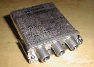
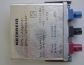
phone: - (Female FME to Female FME) A163 540 02 13 Picture of FAKRA type splitter
Splitter (FAKRA connectors) A163
820 30 89 Cable from FAKRA splitter to
GPS A163
540 09 13 Fem. FME to Black FAKRA Male A163 540 11 13 Aerial (GPS and Phone) A163
820 06 75 or A163 820 18 75 (2nd
part replaced 1st part at some point) Aerial (Phone) A163
827 00 01 or A163 820 11 75 (2nd
part replaced 1st part at some point) Hints for US ML owners US vehicles do not have the
harness between under-the-seat and the radio. Therefore, I expect that to fit
the European UHI kit to the vehicle, you will need to follow the instructions
relating to fitting the UHI kit to MY2002/2003 vehicles and make the wiring
loom. If you want to install the
2002/2003 Nokia 6310i kit, then you can use the part A203 820 31 15 as that
wiring harness, but you may need to change the connector on the aerial cable
where it connects under the front right hand seat to the existing antenna
cable. The A203 820 31 15 part is
an extension lead to extend wiring from the centre console glove box to the
side of the COMAND unit on a C class. It is probably not worth
bothering with the compensator because the US GSM frequency is 1900Mhz, not
1800Mhz. Other interesting UHI information The UHI interface (D2B)
version has 2 connectors, the 25-pin D-Type and the fibre optic connector. The
25-pin connector connects to the UHI cradle connector with 2 power cables and a
8 way (4 twisted pair on ML) shielded cable. Here is the pin-out of the
25-pin connector:
As is probably obvious, the
UHI cradles contain microprocessors and interpret between the �standard� UHI
controller, and the phone supported by the cradle. I hope one day Mercedes will
make a full blue-tooth cradle that means you don�t need to plug in the phone at
all. UHI Telephone Cradles There are regularly new
telephone cradles issued, some replace existing cradles but support newer
phones. If purchasing cradles from ebay, it is important to make sure you get
the correct version. Here are some of the part
numbers
Unanswered Questions There are a number of
questions that I�d love to get answers for: - 1) Is the MY2004 UHI loom between seat and behind COMAND
available, and what is it�s part number 2) Why are there some RHD MY2003 ML�s which seemingly
have old aerial provision on the roof connected to the FAKRA connectors in the
roof? 3) Which vehicles need the splitter with the FAKRA
connectors (is it just MY2001, or did some MY2000 vehicles have this) 4) Is the GPS splitter fitted even if you just have
COMAND (on older ML�s and in USA?) 5) What is A163 540 10 13 – I�m pretty sure it�s
the GPS aerial cable for the Audio-30-APS to connect to the splitter with FAKRA
connectors. 6) What is A163 540 03 13 (I think its similar to above
but with FME connectors) 7) What is A163 540 06 13 (cable harness used in USA) 8) What is the part number for the little purple clip
that the screw which holds the bottom of the phone console into place screws
into 9) What is the part number for the 2 screws that hold
the console bracket to the centre console. Feedback I welcome your feedback,
experiences etc, then I can improve this document, Feedback around fitting to
US vehicles, and to pre MY2002 ML�s would be useful, as this document is
lacking in that area. Feel free to email me with
questions – I do not guarantee any response though � Other documents covering
what I have modified/added to my Mercedes vehicles are at http://www.mercupgrades.com � 2005 - R.P.Almeida Mercupgrades email Thank you to others for
allowing use of some of their pictures. |

If you found this information useful, please support the site by making a donation via Paypal. Any amount at all helps me improve the information on the site. |
Comand Online Ltd - the place to buy Mercedes iPod kits, phone kits, retrofit parts & map disks MY AUTOCAR - THE BEST PLACE TO TALK CARS |