
 |
!! Please select country!!
Created: 29 Jan 2010
Last Updated: 22 Sep 2013
|
** DANGER OF DEATH: YOU MUST HAVE THE DISTRONIC SENSOR ALIGNED BY A MERCEDES DEALER USING THE SPECIAL TOOL OR YOU WILL CRASH *** Introduction: This document describes how to retrofit Distronic to a MY2004 or older SL55. In pre 2005 models the system consists of a Radar sensor and a separate control unit. In later models the distronic system was simplifed so that all electronics was in the distronic radar sensor, so although this document will help you run the wiring loom and install the Distronic switches and sensor, it contains more information than needed, but the author has only installed Distronic in the MY2004 vehicle, so the parts for MY2005 may be wrong, and the wiring loom installation will be subtly different. The pictures are from a Right Hand Drive car, but there is LHD information in this document. Parts Needed: Upto and Including MY2004
MY2005 onward
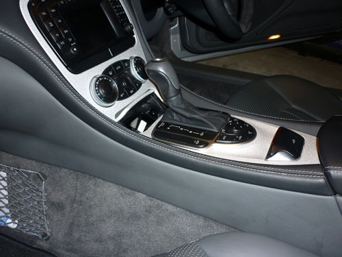
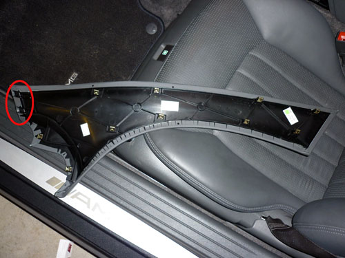
Instructions. Firstly disassemble the centre console in order to install the distronic switch. On RHD cars it is not necessary to remove the COMAND unit as no wiring is run from left to right. On LHD cars I beleive it is necessary to run CANbus wires from passenger side to driver side behind the COMAND. You need to firstly remove the wood (or metal) centre console trim, The pictures below are for the pre MY2005 facelift, however the procedure is the same on newer cars except that you must open the cupholders, remove the front piece and close them again. On MY2009 cars to remove the COMAND you must also remove the airvents above to access the screws that hold the top of the COMAND unit. Firstly remove the trim either side of the centre console. Lower the seats to the lowest and most rearward position to give best access, and then remove the trim which just pulls off from the centre console and then slides out from the dashboard. Put your fingers under the trim (above the carpet) in the middle and pull gently to release the middle clips, work your way backwards until all the clips are released and then pull the trim out (pulling to the rear of the car away from the dashboard). Here is a picture of the trim removed, circled are the hooks that hook into the dashboard, you can also see all the clips that hold the trim to the centre console and the other two metal clips that lock it into the dashboard.
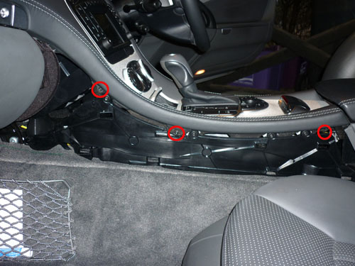
Now unscrew the 3x TORX TX20 screws on each side that hold the wood/metal trim to the centre console. The screws are quite long and the screw at the rear end is recessed so a torch / flash-light is useful.
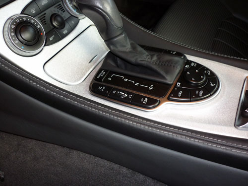
Once that is removed, remove the gear selector knob - move the gear selector to N (ensure the parking break is on and the wheels are chocked), pull up the leather gaitor, rotate the knurled nut 90 degress anti-clockwise and pull the gear knob upward. If the car has keyless go you must not twist the gear knob or you may break the pins from the start/stop switch that plug into the top of the gear selector shaft. On non-keyless-go cars, twisting the knob as you pull upward helps. On MY2005 onward cars, open the cupholders and remove the front panels from the cupholders and close them again - this allows the two tabs at the top of the centre console trim (that cover the cupholder screws) to come forward without hitting the cupholders. Ensure that the ash-tray is closed (remove the insert), and you can then pull up the trim, from the rear, by pulling on it through the hole left by the gaitor.
Pull the whole trim out further by pulling it away from the audio/COMAND unit, the ash-tray does intefere with the gear selector surround, so take care.
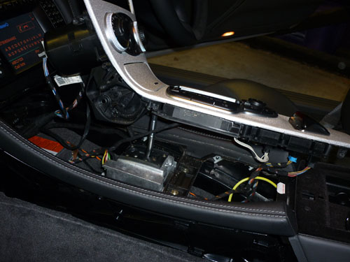
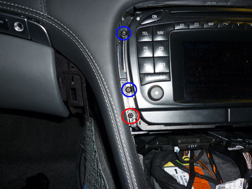
Once the whole trim is released you should disconnect the 3 cables (one pulls straight out, two are on rotating clips) from the airconditioning unit, the cigarette lighter power (pulls out at 90 degress to the body of the cigarette lighter) and the purple connector on the gearbox mode selector (W/S, W/S/M button). Also disconnect the two plugs to the roof / mirror selector switch if you want to remove the whole trim, but you can just lay it to the side if just removing the audio system. You will now see one screw (red in picture below) each side of the cup-holder which hold the cupholder to the frame the COMAND sits it. On MY2002-2004 cars you will also see two screws (blue) each side of the audio unit which you should undo and remove to remove the audio unit.
On MY2005 - MY2008 once the cupholders are removed look in through the exposed slot and there are two plastic lumps on a rail at the rear that hold the back of the COMAND in place. If you push on these lumps (with a wedge or screwdriver) it it allows the back of the COMAND to drop down. The front can then drop down and the whole unit can be removed. On MY2009 onward COMAND is held in by the cupholder screws and there are two additional screws that screw into the top of the COMAND. To access these screws the vents above COMAND must be removed. This is done by removing the speaker grill above them exposing two screws, undo those screws. There are then two hook catches (one at the bottom of each vent) which can be seen through the vents - these are best released with the Mercedes pulling hook tool which will release and pull the whole vent forward. You can then access the screws that hold the front of the COMAND in from above. When re-assembling ensure that the wiring does not get caught in the ash-tray mechanism, and that all wires are plugged back in again.
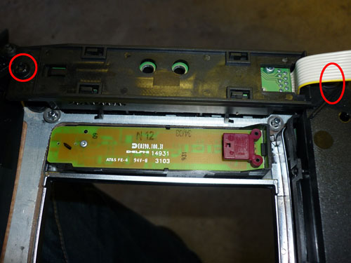
7/Dec/2010 V1.2 expand info on removal of MY05-MY08 COMAND further. Now remove the 2 Torx screws and connector holding the switch, install the new switch
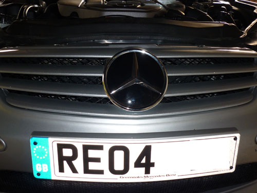
Do not re-assemble the centre console at this point as removing the trims above the footwells requires the console sides to be removed and it is easier to run the wiring across the car behind the COMAND unit. Remove the 4 bolts that hold the radiator grill, pull the top forward slightly and bang the bottom back toward the car with your hand and it will unclip from the bumper. This picture shows 2 of the screws: -
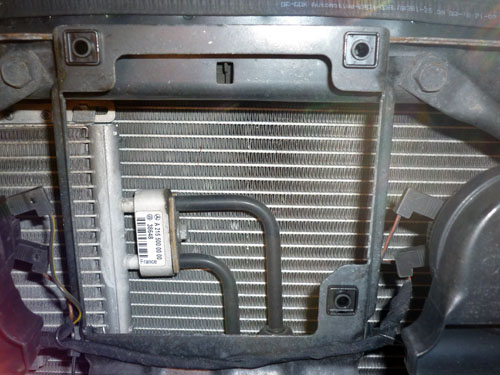
Install the distronic sensor - you can see from the picture below the captive nuts installed from the bolt kit.
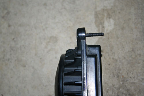
Here is a picture of the sensor with the new bolts installed. If installing new bolts into the sensor, install the plastic nut holder into the distronic sensor, then put the screw into it. Put a load of washers and a nut on the other side and tighten the screw until it locks into the plastic nut holder (it will not be able to fall out, and will thus hold the sensor it place proud of the mounting bracket as shown in the picture below: -
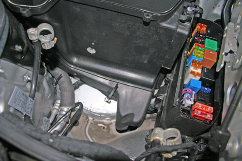
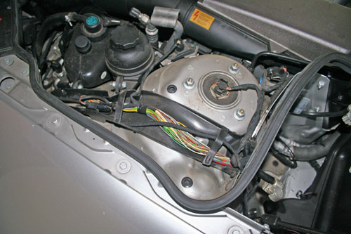
Now install the wiring loom. It goes from the sensor, to the fusebox (where it can enter the body of the car through the hole in the bottom of the fusebox), to the controller which is mounted on the control-unit plate below passenger's feet, to the engine CANbus distributor, to the diagnostic socket connection point and to ground. (Please note that the MY2005 onward loom only connects fusebox, sensor, ground and CANbus distributor) Place the car somewhere where there is lots of light and the bonnet can be opened to its maintenance position (which is fully upright). Now disconnect the ground of the battery in the trunk (boot) and tuck it away so it can not accidentally reconnect. Then disconnect the ground than positive of the battery in the engine bay. Do not even consider leaving doing this in the wrong order or removing just the connection in the engine bay - the battery management system can connect the 2 batteries together if it thinks the trunk battery is low. Also remember that once you do this the seats will not move. Remove the vent cover from the air intake behind the battery in the engine, and undo the clamp and remove the battery. Now remove the support plate that holds the battery in place (3 10mm bolts) and the cover of the fusebox. It will now look like this: -
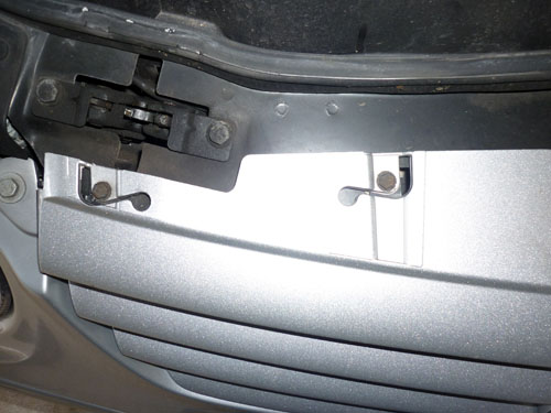
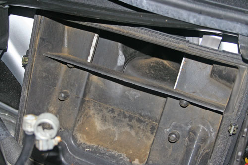
Now remove the air intake. This is done by removing the wiring from the sensor that is part of the intake, and then unclipping the two catches at the top of the vent, and pulling up the rain water catcher, it uncips from the windscreen. If you can easily remove the wipers that will make life easier, but I managed to remove the air intake without. The picture below shoes the front of the air intake removed and the back section which remains in place. You can see the 1 of the 2 silver clips at the top (right) which hold the top edge, the bottom edge clips into the bottom of the box, but the box is also held together by the two spring clips visible at the sides, so after unclipping the top clips, you have to tug the top and fold it down about 1" before you can unhook it from the bottom.
Now remove the 4 screws that holds the top section of the fusebox to the bottom and remove the top of the fusebox and pull out the fusebox "fuseholder" section (which is in fact the passenger side front SAM) enough to expose the wiring path.
Remove the top of the cable duct in the engine bay (you will have to pull the rubber seal up at the end where it passes into the battery area as that holds the end of the duct cover.
Remove the rubber grommet where the cables come into the fusebox from the engine bay, roughly in the middle of the fusebox. Feed the wiring loom through - I found it easier to do this from the the engine bay to the inside of the vehicle. Insert the grommet of the wiring loom into the place vacated by the rubber grommet previously removed, plug the fuse into the empty postion 45 (49 is at the edge of the fusebox) and re-assemble the fusebox. This picture shows the cable installed in the fusebox, but the fuse carrier is not yet plugged into position 45: -
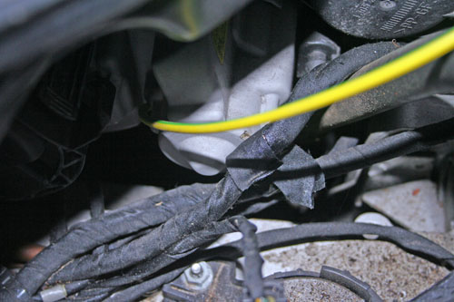
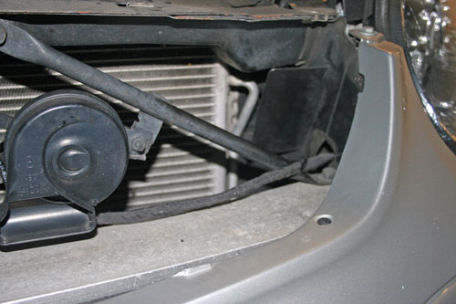
Route the wiring along with the other wiring (cable tie it to that wiring), through the duct, under the headlight to the sensor. The yellow plastic wire in the photo below shows where the cable will go under the headlamp: -
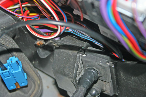
And the picture below shows where the cabling passes from the sensor through the plastic grommet and under the headlamp: -
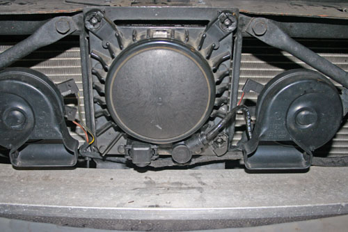
Picture of sensor plugged in: -
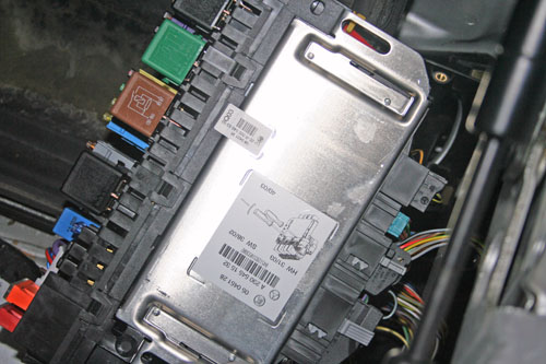
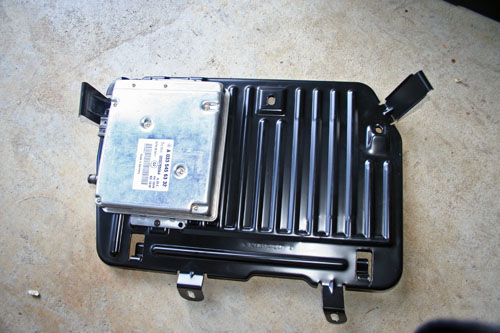
Please ensure you cable-tie the loom so it can not move and get caught or damaged by the radiator/fan/etc (look at how the horn cabling is cable tied). Connect the earth lead to the earth point in the footwell. Install the distronic control unit on the footwell plate and plug in and reinstall the footplate. Picture of distronic control unit attached to footplate: -
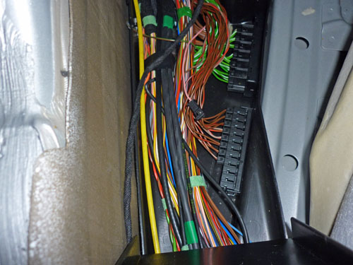
Run the other 2 wires of the loom to the "engine" CANbus distributor on the left hand side and the pink wire to the connection near the diagnostic socket. On RHD cars these are both in the left hand wiring duct under the front carpet. On LHD cars I beleive the CANbus distributor is on the right hand side but the diagnostic connector may be on the drivers side. Picture of the driver's side wiring duct on a RHD SL55.
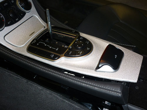
You can see the pink diagnostic connection for distronic, and the interior and engine CANbus distributors. The engine CANbus distributor has the green/green-white pairs. Reassembly: Once everything is complete, re-assemble the car (including the radiator grille which protects the sensor) re-connect the batteries (engine bay battery first, postive then ground) then trunk (boot) ground cable and take the vehicle to a Mercedes dealer for coding and most importantly for distronic sensor alignment. Because the battery has been disconnected, you may have to turn the steering from one end to the other a couple of times to re-initialise the steering-angle-sensor if you get an ESP error on the cluster. Alignment and Coding: Apart from the alignment of the distronic sensor the dealer will have to do the following coding to enable distronic: Drive/Engine Management: Either have Option 218 added to the datacard and SCN code the Engine Management system (best), or using Star Diagnosis with 'Factory Mode or Developer key' and enable Distronic/DTR. (nb. if you don't have option 218 added to the datacard and the engine management system is SCN coded in the future, then not only will distronic not work, but there will be an ESP error and various other issues). Body/System Diagnosis: Enable DTR/Distronic. (This is for diagnosis purposes). Body/CGW: Enable DTR/Distronic. (This tells the lower control panel and ESP the car has Distronic, so once this is done the button for distronic will light up). Info & Communication Systems/Instrument Cluster: Enable DTR/Distronic. (This enables the menu on the cluster). ** DANGER OF DEATH: YOU MUST HAVE THE DISTRONIC SENSOR ALIGNED BY A MERCEDES DEALER USING THE SPECIAL TOOL OR YOU WILL CRASH *** Finshed pictures: Distronic Switches:
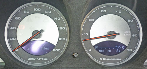
Distronic display on cluster:
Version 1.0 7th March 2010 |
If you found this information useful, please support the site by making a donation via Paypal. Any amount at all helps me improve the information on the site. |
Comand Online Ltd - the place to buy Mercedes iPod kits, phone kits, retrofit parts & map disks MY AUTOCAR - THE BEST PLACE TO TALK CARS |